Today the museum is closed

Map

Exhibit description

Railway crane EDK25-372

Exhibit design

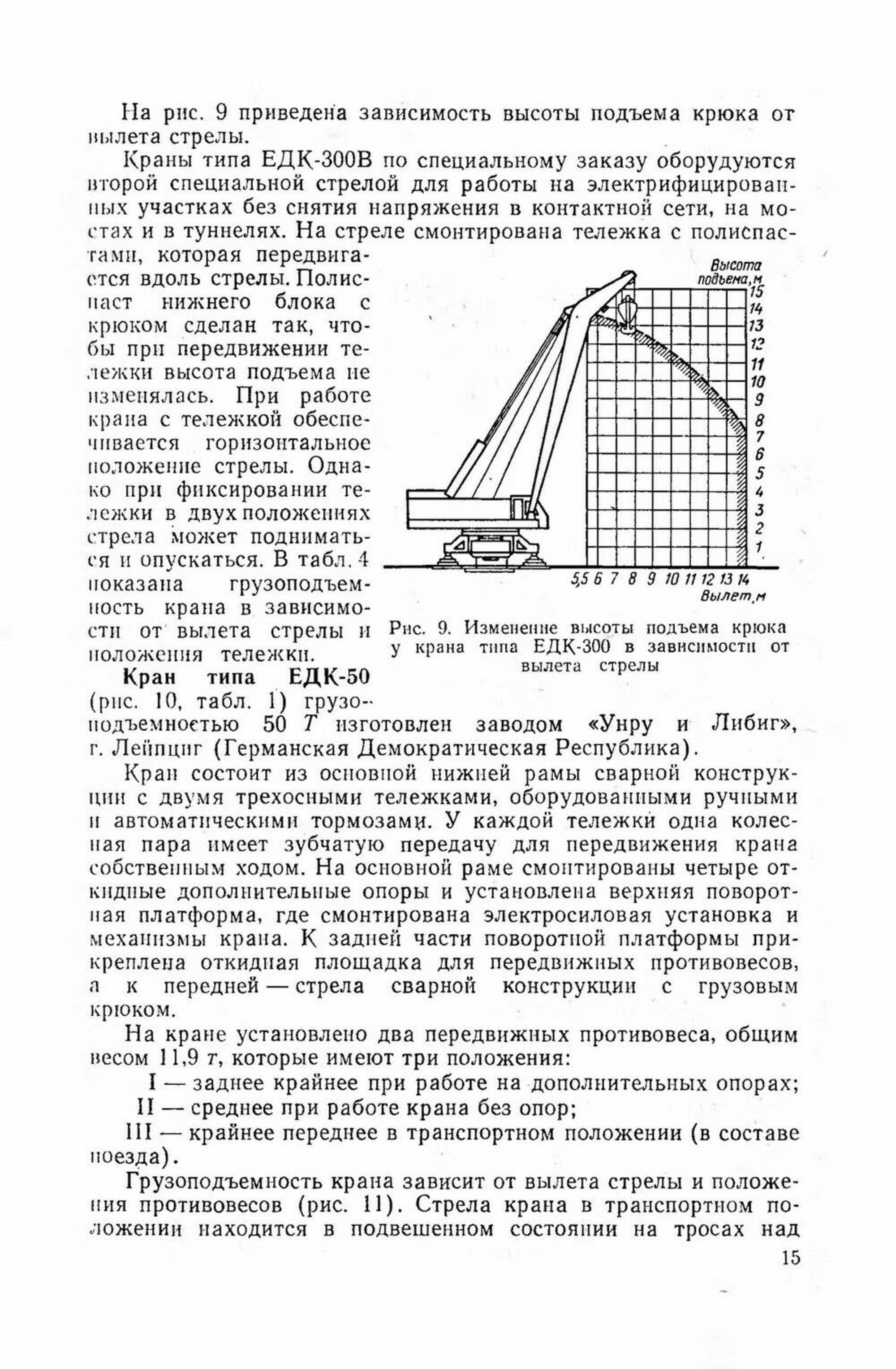
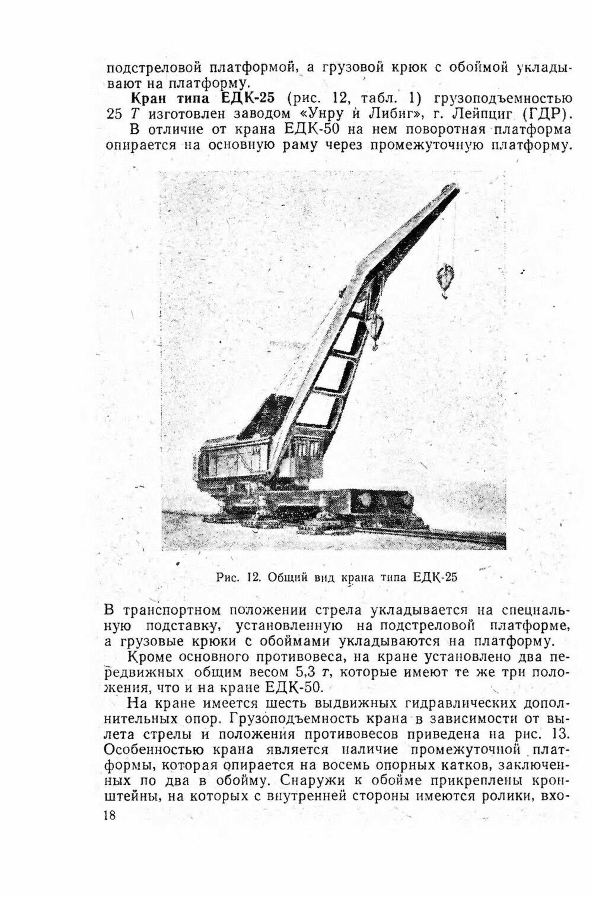
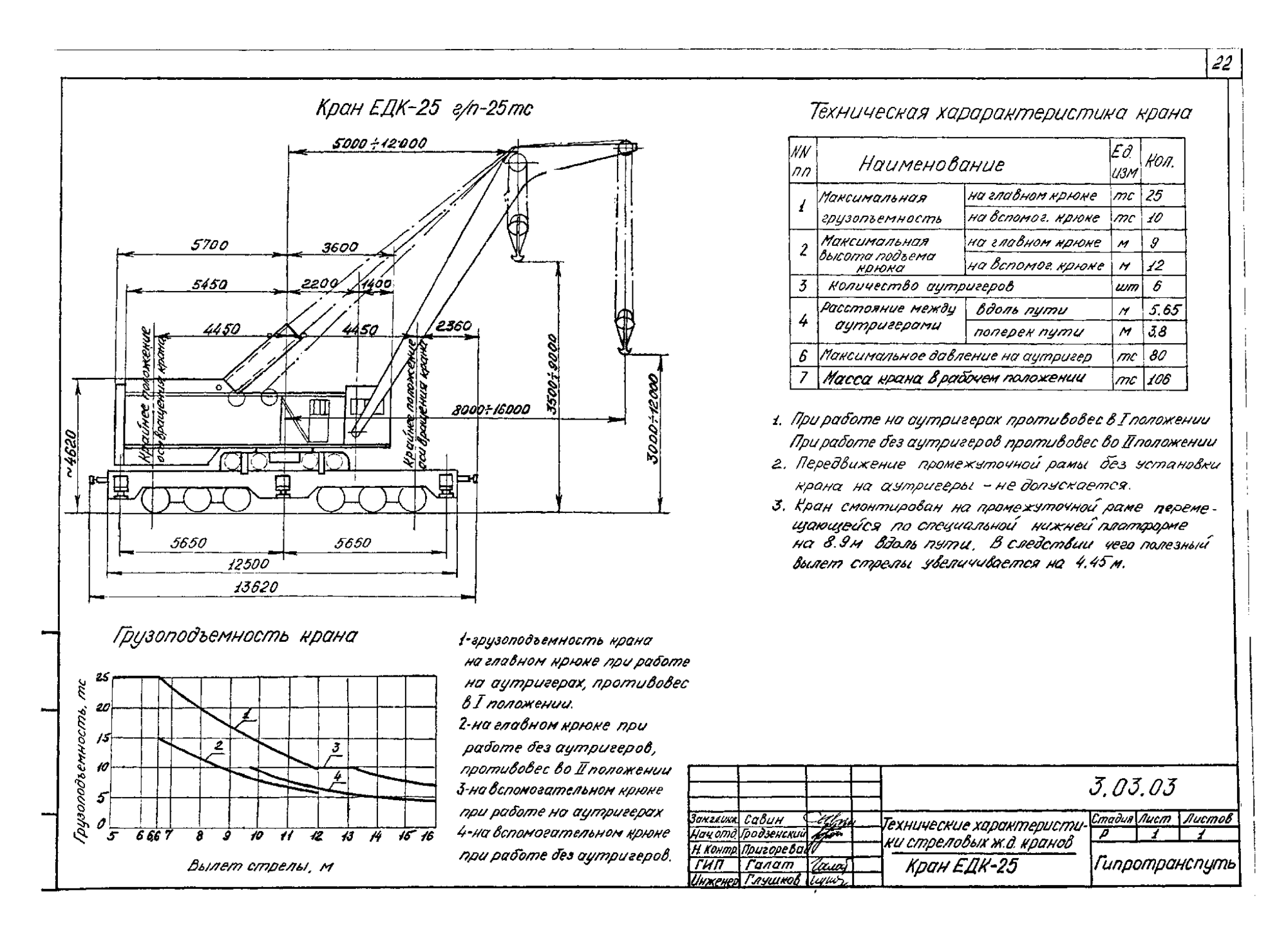
The crane consists of a lower platform of a welded structure on two three-axle bogies with pneumatic and hand brakes. Each bogie has one axle equipped with a gear reducer with a gear transmission for moving the crane under its own power. Six hydraulic outriggers are installed on the frame for stabilization when working at large boom extensions and with a large load.

An intermediate platform is installed on the lower frame, which can move along the crane. It contains a rotating platform with a diesel-electric unit. On one side, it has mounts for a welded boom with a load hook, and on the other, a folding platform for retractable counterweights. The crane is equipped with two mobile counterweights with a total weight of 5.3 t, which have three positions. In the rearmost position, the crane can work with outriggers, in the middle — without them, and in the extreme forward position it can be transported.

The design uses an intermediate platform supported by eight rollers, two in a cage. Brackets are attached to the outside of the cage. On the inside, they have rollers that enter under the shelf of the main beam of the lower frame and prevent the intermediate platform from tipping over. The rotating part moves along the lower frame by 8.9 m, which allows one crane installation to service a site of 41 × 32 m.

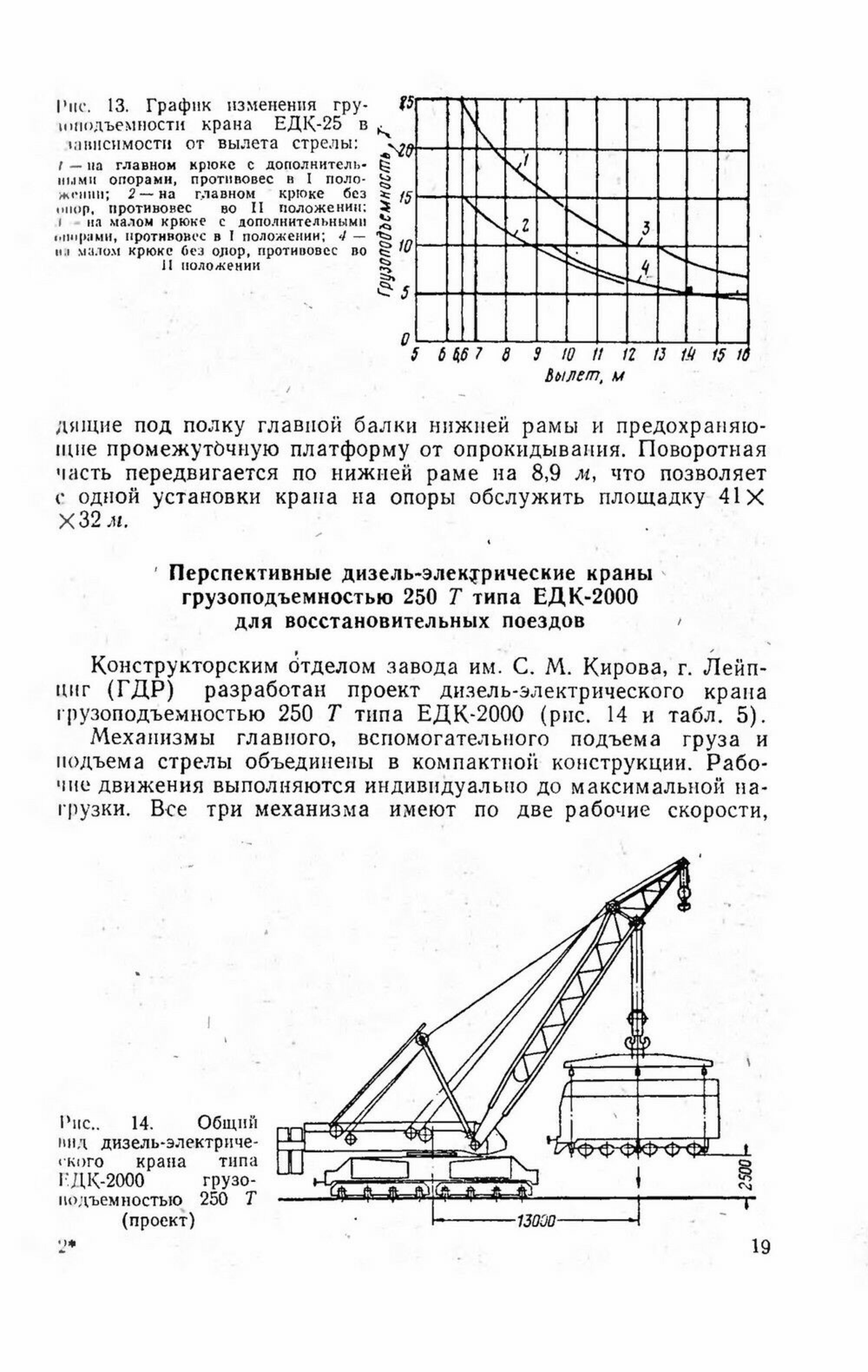
The lifting capacity depends on the boom reach and the position of the counterweights. Maximum — 25 t. The crane is equipped with a diesel engine with a capacity of 100 hp, driving an electric generator with a capacity of 48 kW. Three-phase power voltage, 380 V. Minimum radius of passable curves — 80 m, length over buffers — 13,620 mm, crane weight in transport position — 106 t. During transportation, the boom is placed on a special support installed on the under-boom platform, and the hooks with clips are placed on the platform floor.

A special feature of the EDK25 crane is the presence of an intermediate platform on which the rotating part with the boom is located. The platform has the ability to move along the main frame by 8.9 m. This allows one crane installation to service a 41x32 m site.

The crane's lifting capacity depends on the boom reach and the position of the counterweights. The maximum lifting capacity is 25 t on the main hook and 10 t on the auxiliary hook.

Parameters

Technical
specifications

Load lifting speed, m/min
3
Swing speed, rpm
1
Maximum lifting capacity, t
25
Crane weight in working condition, t
80
Crane speed under its own power, km/h
0.9
Crane speed in a train, km/h
65
Minimum radius of passable curves, m
80
Number of axles
6
Number of bogies
2
Main frame length, mm
13,620
Frame length without buffers, mm
11,420
Rail pressure, t
17.6
Distance between bogie supports, mm
5,550
Distance between axles, mm
1,550
Crane width, mm
3,150
Crane height, mm
4,620
Crane weight, t
106
Drive
Diesel-electric
Number of cylinders, pcs.
4
Power, hp
100
Number of revolutions per minute
750

Drawings
and diagrams

History

Chronology

  1. 1950s Railway 25-ton cranes are designed for emergency repair, assembly, loading and unloading operations. A representative of this class of cranes, the EDK25 crane, is typical of the 1950s and 1960s. It was fundamentally different from the cranes built before the war and in the early 1950s due to the transition from a steam power plant and mechanical drive to a diesel-electric drive. This greatly simplified both the mechanical part of the crane and its maintenance, and most importantly, it became easier to operate the mechanisms. They switched to a hydraulic drive in crane control in the early 1970s. This type of drive is still the main one today. It allows for smoother and more accurate work on moving loads.
  2. 1953 The rail-mounted crane was built jointly at the Kirov Plant in Leipzig and the VEB LOWA railcar plant in Weimar (GDR) in 1953.
  3. 1996 The EDK25-372 rail crane was delivered to the museum from recovery train No. 4021 (Tver) of the October Railway in 1996.