Today the museum is closed

Map

Exhibit description

Freight electric locomotive VL8-1522

The most powerful

The VL-8 electric locomotive was intended for heavy freight service on tracks electrified with direct current with a voltage of 3,000 V. The total power in two sections was 4,200 kW in hourly mode. The most powerful FD series steam locomotive at that time had a maximum power of up to 3,000 hp. or 2,200 kW.

The locomotive was formed from two permanently coupled sections with two bogies in each. The body was made of carbon steel, there was a supporting center beam weighing 90 tons.

The carriage was built on the principle of the VL22M electric locomotive, in which the bogies are connected to each other by hinges, and the sections — through the bogie frames and automatic coupling. The body of the electric locomotive did not carry the transmission of traction force and rested on the main central supports above the bogies, and also had additional supports located at the ends of the body. The axle boxes of the experimental machine were made on spherical roller bearings, later replaced with cylindrical bearings.

When designing the body, a wagon layout was chosen. The experience of operating the VL19 and VL22 electric locomotives, where the entrance to the driver's cabin was from the front platform, and the door was in the front wall, was unsuccessful due to the blowing of cold air. A through passage was arranged between the sections for the convenience of servicing the electric locomotive and quick transition from one control cabin to another. Access to the cabin was provided through hinged doors located on the sides of the section.

The latest NB406A engines with an unsaturated magnetic system were designed for the electric locomotive, making it possible to achieve maximum traction performance in a wider frequency range. A two-runner pantograph P-Z designed for long-term current was installed on the electric locomotive.

The design speed was initially set at 90 km/h, in 1957 for serial locomotives it was raised to 100 km/h. One of the advantages of the electric locomotive was its equipment with regenerative braking, which operated at speeds from 12 to 100 km/h.

Many people remember them for pulling passenger trains, including the branded "RITSA" (Moscow-Adler) or "Northern Palmira" (Leningrad-Adler) along the Black Sea coast.

Parameters

Technical
specifications

Type of service
Cargo
Design speed, km/h
100
Hourly mode power on traction motor shafts, kW
4,200
Hourly mode traction force, kN
319.7
Electric locomotive speed at hourly mode, km/h
42.6
Continuous mode power on wheel rim, kW
3,660
Continuous mode traction force, kN
297.5
Electric locomotive speed at continuous mode, km/h
44.3
Tractive force on estimated grade, kN
456
Speed ​​at estimated grade, km/h
43.3
Operating voltage (DC), V
3,000
Electric braking
Regenerative
Electric motor power at hourly mode, kW
525
Electric motor power at continuous mode, kW
470
Number of stages of weakened excitation of traction motors
4
Maximum weakening of excitation of traction motors
64%
Gear ratio
3,905
Wheel diameter, mm
1,200
Rigid wheelbase, mm
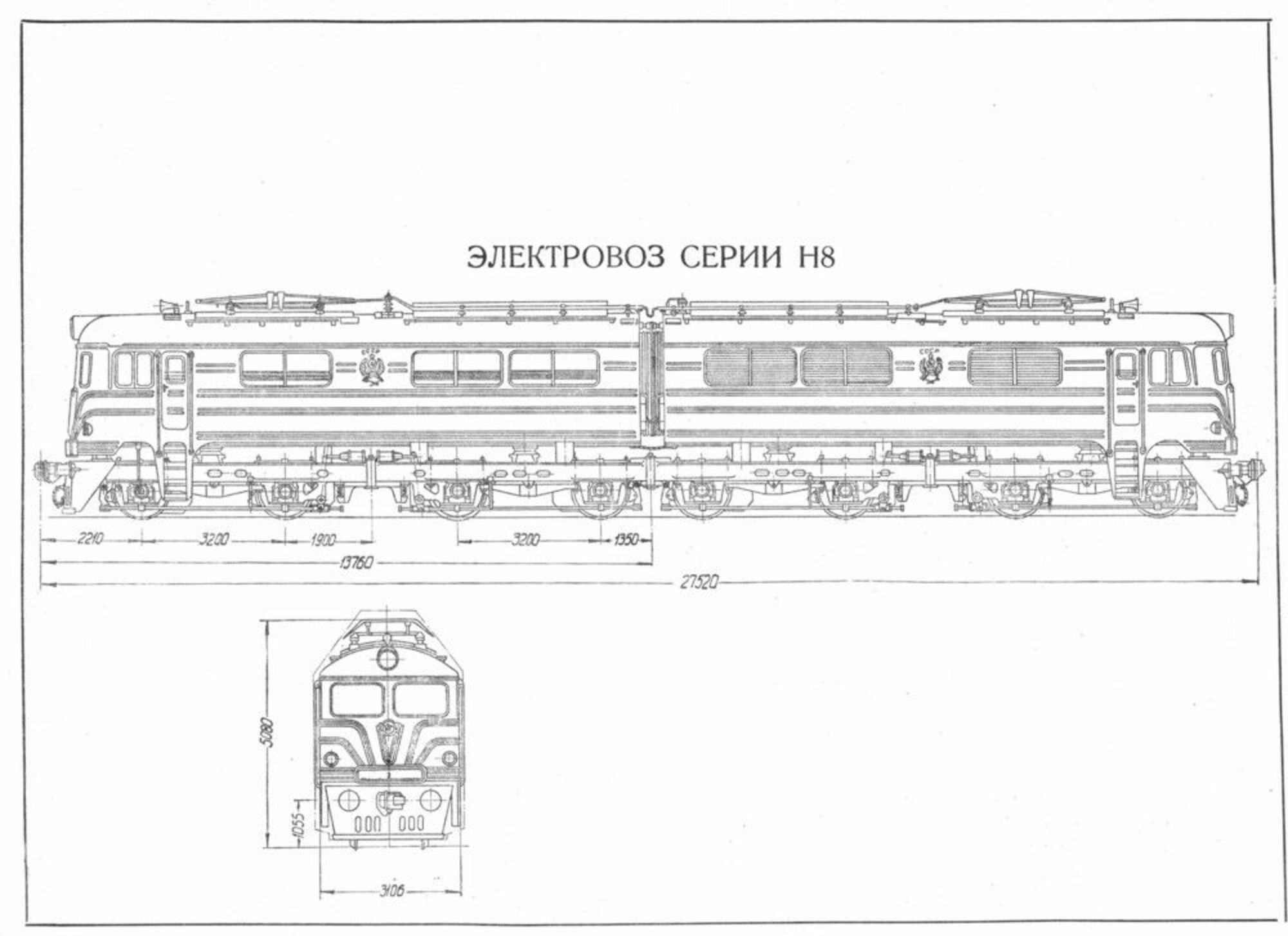
3,200
Total wheelbase, mm
24,200
Length of locomotive by axles of automatic coupling, mm
27,520
Capacity of sand bunkers, m³
3.92
Height, m³
5,080
Length, mm
2 × 13,760 = 27,520
Width, mm
3,106
Minimum radius of passing curves, m
80
Weight (without sand), t
180
Coupling weight equipped electric locomotive, t
191.2
Load of wheelset on rails, t
23.9

Drawings
and diagrams

History

Chronology

  1. 1723 A total of 1,723 vehicles were produced in eleven years. NEVZ produced 430 units, numbers 001–200 and 1201–1431, TEVZ — 1,293 vehicles, numbers 201–1200 and 1432–1723.
  2. 1949 With the gradual electrification of freight-intensive highways, an electric locomotive capable of replacing the VL22M electric locomotive became necessary, even operating on a multiple-unit system (i.e. two electric locomotives). Therefore, back in 1949, the preliminary design of an electric locomotive began: the choice of its parameters, wheel arrangement, power, and type of electrical equipment.
  3. 1952 The development of a 3,000 V DC locomotive designated H8 began in 1952 at the Novocherkassk Electric Locomotive Plant. At that time, the transition from 1,500 V to 3,000 V was already underway. In the spring of 1953, a prototype H8-001 was released. The number 8 in the name meant the number of axles of the locomotive, H - Novocherkassk Plant.
  4. 1955 In 1955, a pilot series of seven locomotives, N8-002 — N8-008, was manufactured. The H8 electric locomotive was put into serial production in 1956. It was necessary to increase production and redistribute production capacities, so the assembly of locomotives was organized at the Tbilisi Electric Locomotive Plant. There, serial production of the machines began in 1958 under the T8 series.
  5. 1963 In January 1963, the name of the locomotives was changed from N8 to VL8, similarly for the electric locomotives of the Tbilisi plant — from T8 to VL8. VL — Vladimir Lenin, 8 — eight-axle. This was done for ideological reasons and at the suggestion of the director of the Novocherkassk Electric Locomotive Plant (NEVZ) P. I. Abroskin and the Deputy Minister of Railways P. G. Muratov.
  6. 1967 The serial electric locomotives differed slightly from the prototypes. Their production continued until 1967. The production of all-metal section bodies and cast bogies was organized at the Lugansk Diesel Locomotive Plant from July 1957.
  7. 1976 In 1976, the MPS fleet still had 1,716 locomotives, but by the early 1990s, almost all of them had been written off from inventory.
  8. 1997 The electric locomotive arrived at the museum from the Povarovo depot of the Moscow Railway in 1997. It was assigned to the South Ural Railway in 1966, and to the Moscow Railway in 1973.