Today the museum is open from 10:00 to 18:00

Map

Exhibit description

Water supply device Hydraulic column

Water supply system

Water consumption in the days of steam locomotives reached colossal volumes. The water supply in the tender of freight locomotives was enough for 50–70 km of travel, and for passenger locomotives — up to 150 km.

Domestic water supply was arranged at stations 50 km from each other. In waterless areas, water was brought in. Supplying such a large amount of water required special devices for its accumulation and creation of a powerful pressure so that its collection did not take more than 8–20 minutes.

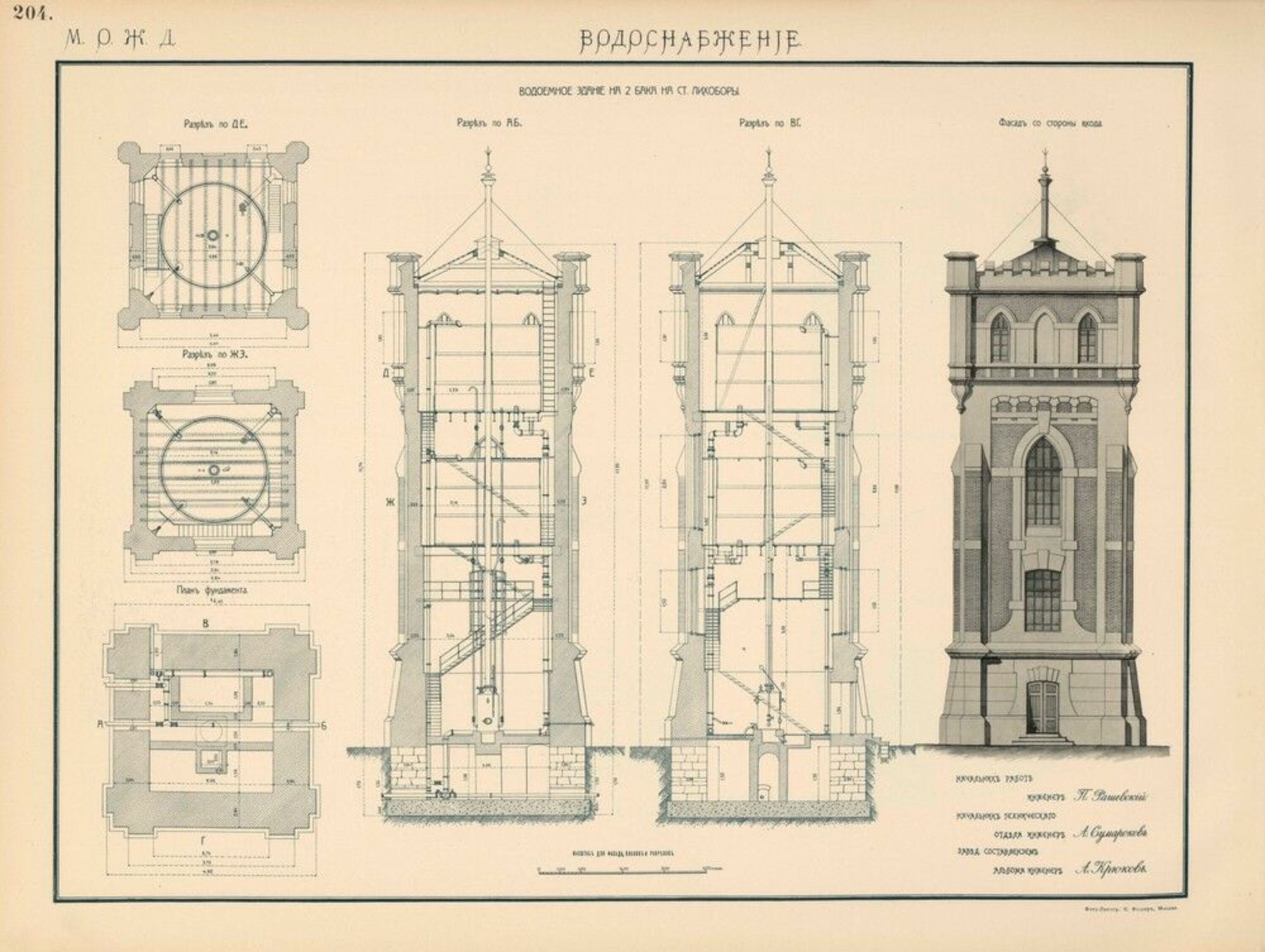
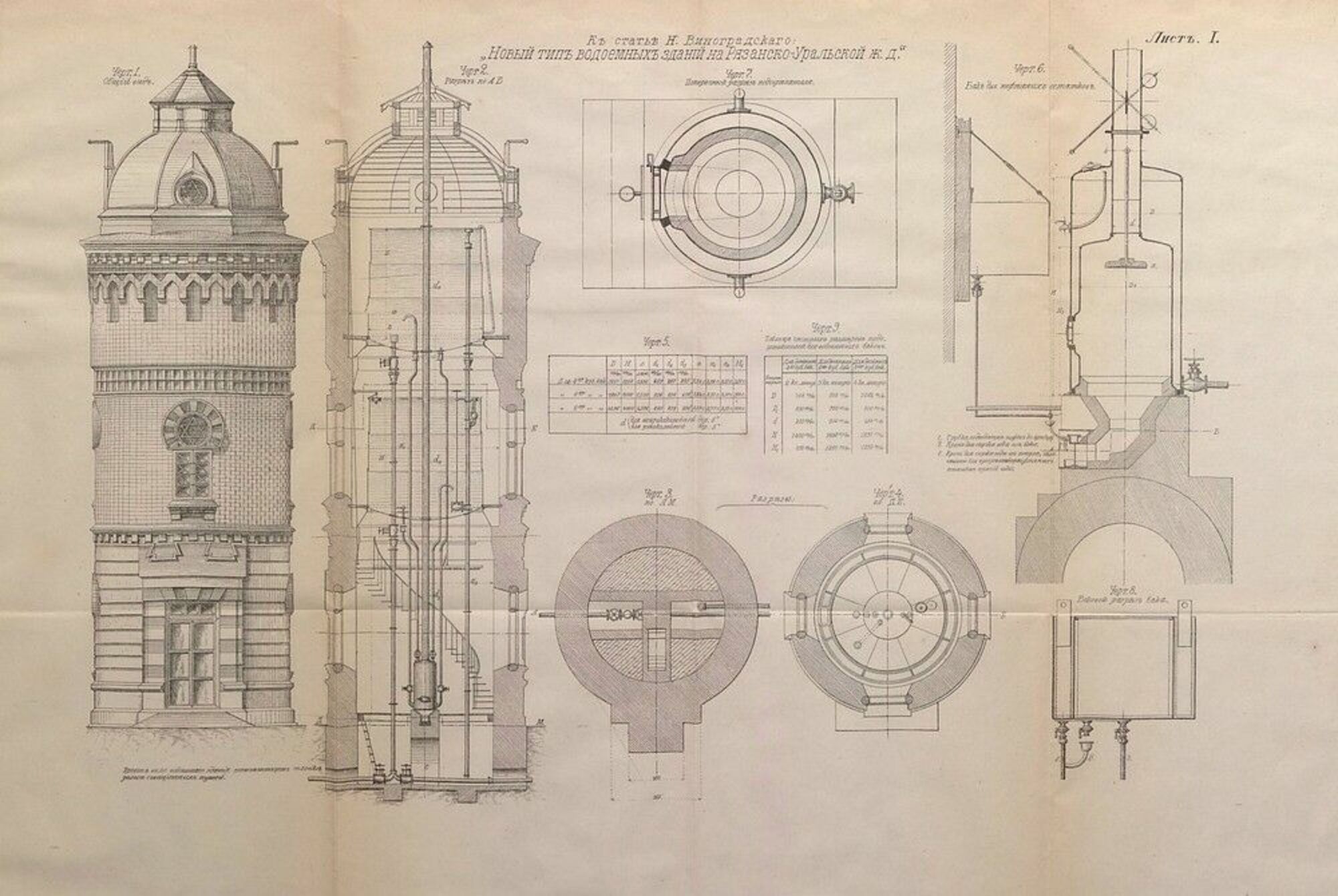
Water towers served as such devices. They had a brick or stone octagon at the base, on which a water collection tank with a capacity of 60–75 m3 was installed.

Water was supplied through pressure mains laid underground below the freezing line of the soil. Various columns were also used here: collapsible, fire, for watering horses, locomotive.

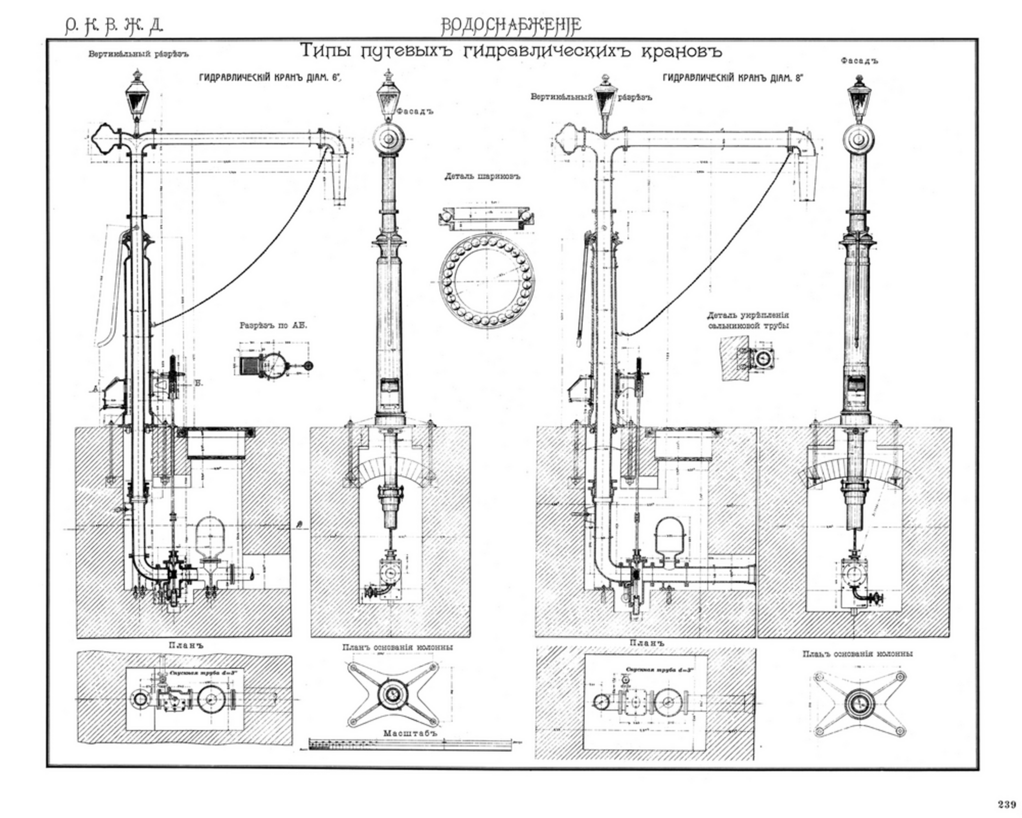
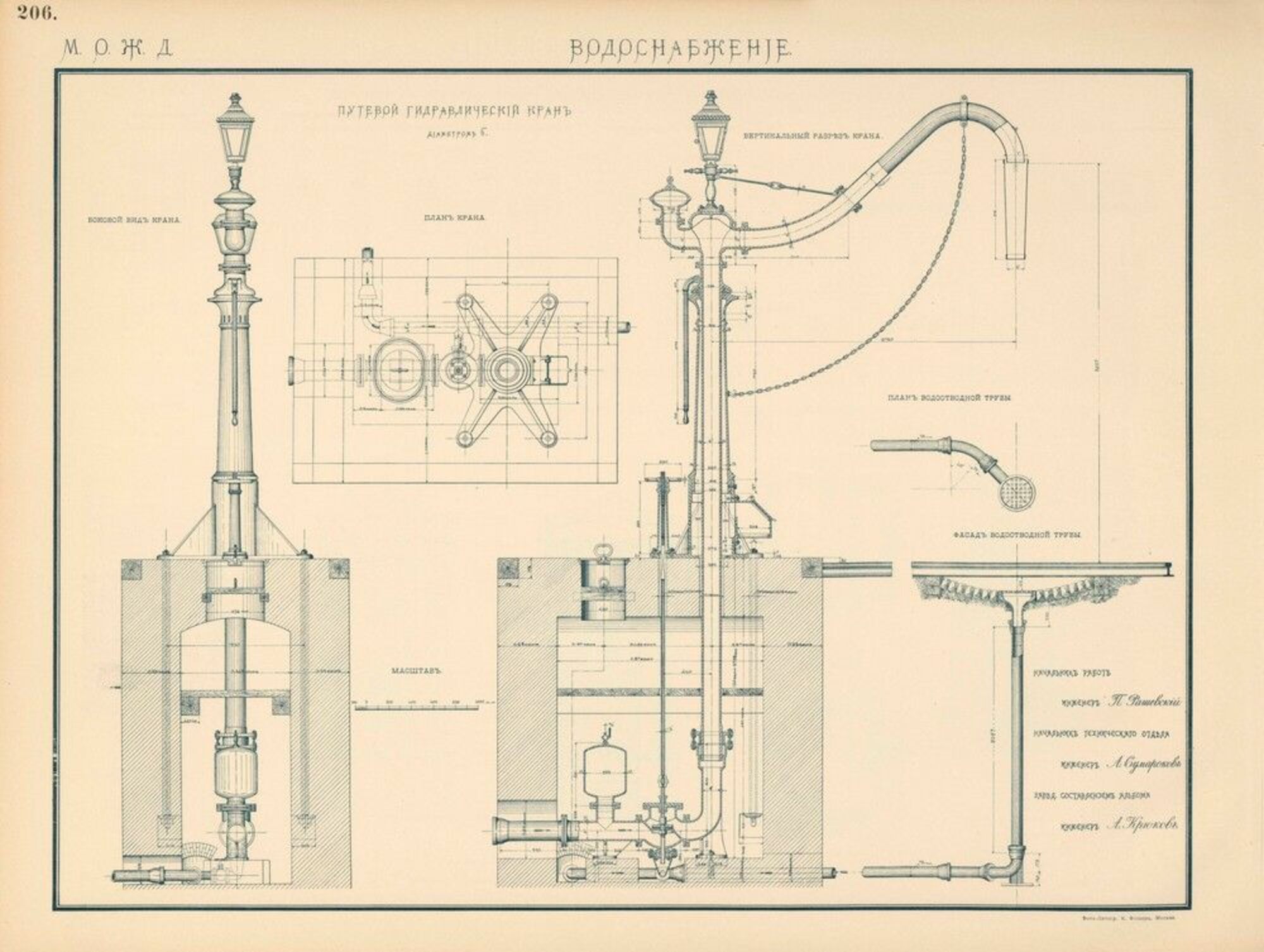
Hydro columns were of two types in design: wall-mounted and intertrack. Wall-mounted ones were fixed to the walls of water towers that stood along the track. Such columns had dispensing trunks.

Track hydro columns were installed in close proximity to the tracks. The track crane consisted of a vertical rotating cast-iron pipe with a horizontal filling trunk. A flow-calming cone was hung on the trunk. The filling pipe was installed on a cast-iron pedestal. At the top of the filling pipe there was a lantern, at night it signaled its position relative to the tracks.

The design of the crane provided for the rapid and complete removal of water from the vertical pressure pipe to prevent rapid freezing. Additionally, in winter, a stove was installed here, the heat from which also went into the underground space. Later, special accelerator devices began to be used to collect water. The simplest of them is a tank installed on a hydraulic column, into which water was collected between refueling of steam locomotives.

In the museum

Pumping stations or water pumps were installed almost everywhere to supply water. Special buildings were built for the pumping station, which were sometimes attached to the water tower.

In 2017 the hydraulic column was added to the exposition of the Museum of Russian Railways in St. Petersburg.

Railway construction most often began in areas that had not been developed in the course of economic activity. There were no highways (dirt roads) there. Already at the stage of surveying and tracing new lines, sources of water supply for economic and domestic purposes were sought. Artificial reservoirs were also created, in which water was accumulated from natural sources, as well as during the melting of snow and rain. Water was needed for economic purposes, primarily for steam locomotives, which were then the only type of locomotives. It was necessary not only to find a source, but also to determine its productivity, as well as to determine the quality of the water itself, that is, whether it could be used in locomotive boilers and for domestic purposes.

The water for feeding locomotive boilers should not be cloudy and hard, or contain substances that destroy the walls of the boiler. Hard water is water that contains a significant amount of dissolved mineral impurities in the form of carbonic, sulphate and chloride compounds of calcium and magnesium. Its hardness was determined by the amount of salts present, and in the case of increased hardness, the water had to be subjected to special treatment in order to soften it. And the water that was used for household needs should not contain substances harmful to humans, pathogenic bacteria, or living organisms. It also should not have a smell.

Supplying such a large amount of water required special devices that would accumulate it and create a powerful pressure. The collection of water should not have taken more than 8-20 minutes.

The main accumulator and distributor of pressure water supply were water towers, which were previously used in industrial production.
Parameters

Technical
specifications

Pipe diameter, mm
200
Service radius, mm
2,900
Height of lifting part from rail head to drain elbow cutoff, mm
3,780
Column installation depth for northern regions, mm
3,250
Column installation depth for southern regions, mm
2,250
Weight, kg
1,820
Price, RUB
300
Manufacturer
V. V. Vorovsky Tikhoretsky
Economic Council
Krasnodar

Drawings
and diagrams

History

Chronology

  1. 1851 In 1851, the Moscow-Petersburg Railway was opened to ensure proper movement. Water towers were installed in pairs next to the main tracks to save time for steam locomotives to fill with water. Distribution taps (hydrocolumns) were installed directly on the walls of the towers and were a hinged pipe that could rotate in a horizontal plane. When the traffic and number of steam locomotives used increased, this was abandoned. They switched to building towers near the tracks with a distribution network from them.
  2. 1930s Water supply during the construction of railways, perhaps, played the first and key role. Steam locomotives consumed a huge amount of water. Thus, the water supply of steam locomotives at the end of the 19th century was 16 tons with three-axle tenders, and with four-axle tenders it reached 23 tons. By the mid-1930s, the appearance of such powerful steam locomotives as FD and IS required the use of six-axle tenders that could hold up to 50 tons of water. The tender's water supply was sufficient for 50-70 km of travel for freight locomotives, and for passenger locomotives - up to 150 km. One can imagine how complex and powerful the water supply had to be. Therefore, domestic water supply was arranged at stations, which were ultimately located at a distance of up to 50 km from each other. In waterless areas, water was brought in. Sometimes, in addition to the water supply in the tender, water was used in an additionally attached tank.
  3. 1936 Direct water supply to the locomotive tender was carried out by hydrocolumns, which were of two types in design: wall-mounted, described above, and intertrack (track). The exhibition includes a hydrocolumn model of 1936. In the post-war period, such hydrocolumns were manufactured by the Tikhoretsk Plant named after V. V. Vorovsky.